Hi all, I'm going to use this thread to document and share my experience on retrofitting Front Park Distance Control (PDC) and all necessary disassemblies on my F30.
I'm attaching EBA 2338017 which is the official installation instructions for this retrofit which applies to F30 F31 F20 and F21 .
This is the necessary parts list for a Sapphire Black F30 with a non M front Bumper:
Description Part number #
Install.kit, Park Distance Control,front 66202338070 1x
Repair kit for bracket, bumper, front 51117324343 1x
Ultrasonic sensor, black 66209261582 4x
Cable Set Front bumper 61129260019 1x
Unit, center console
61319252912 1x
Center console control unit retrofit cable (included in 66202338070)
Decoupling ring PDC torque converter 66206923000 4x (included in 66202338070)
Center console unit
 Cable Set Front bumper 61129260019
 Install.kit, Park Distance Control,front 66202338070
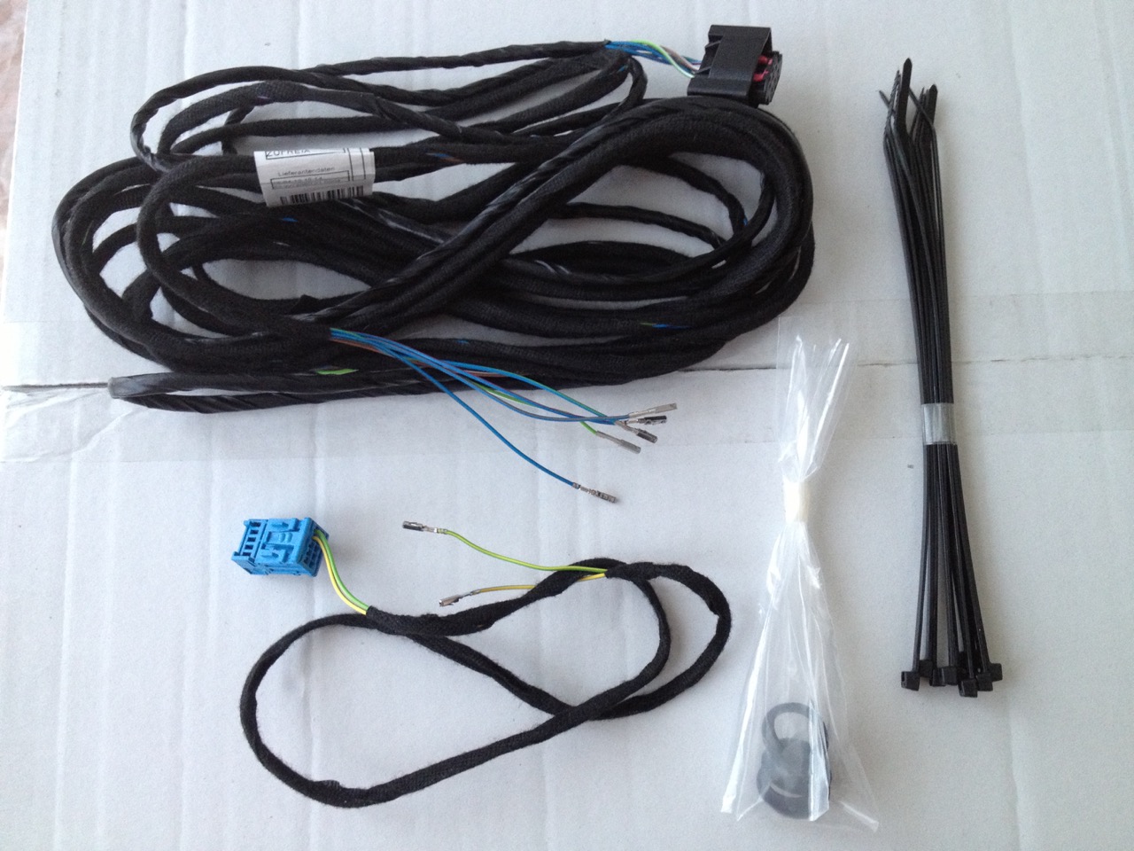
Included:
- Front PDC retrofit wiring harness
- 4x PDC Rings
- 10x cable ties (instructions specify 20x)
- Centre console control unit retrofit cable
Repair kit for bracket, bumper, front 51117324343

Included:
- 4x PDC sensor holders
- 2x headlight washer holders
- 2x camera + PDC holders for Parking Assist
Edit 2013-07-28:
- added photos of the parts
- mention "Centre console control unit retrofit cable" and the sensor rings are included in the installation kit
Edit 2013-09-29:
- added photos of the installation and the Centre console unit
Edit 2015-05-10:
- added Centre console wiring info
Installation
Disconnect car battery!!!
I started with the Center console change.
For that we start by getting access to the console pulling the leather from the shift handle:

Then the button unit is fixed by two plastic springs on opposite ends:

The easiest way is to press on the top one by hand:

then on the 2nd one with a tool on the pointed area (you have to try and feel it):
The instructions state that a cable should connect pin 2 on the console to the ICM and on my car that was already connected.
What the instructions are missing is pin 1 and in the end the connections should be:
Centre Console <-> ICM
PIN1 GN/GE(Green/Yellow) wire <-> PIN28
PIN2 GE/BL(Yellow/Blue) <---------> PIN6 should already be connected
PIN3 <-------------------------------> PIN13 should already be connected
Notice: as you can notice from the pics of the kit, it comes with an extra 10 pin blue plug and with 2 cables, connected on pin 2 AND pin 1.
Assemble back the new console.
Front Bumper
Disassembly of the front bumper is pretty straightforward, just too many bolts

You'll have to get half of the bolts out of the front wheel inside trim to access some bolts for the bumper and disconnecting the fog lights and headlight washers if you have them.
On the guides for the PDC holders, drill the holes carefully to 18mm. Most probably you'll have to debur a little because with a perfect 18mm hole the sensors won't fit.
I tested each sensor on the hole without the holder to see when they fit perfectly
Go slow, go perfect
The PDC Holders have markings for their position: VLA, VLI, VRI and VRA
That is the order from left to right, when you're working inside the bumper
L for Left
R for Right
A for Outside
I for Inside
Firewall
Firewall access is actually pretty easy.
Start by getting the cover out of the battery connector. Has a red cover, can't miss it.
What I actually missed was a hole used for this cover, and actually used it to guide the cable through but only found that out in the end. Either way, I didn't found a better way to route the cable. Do your own analysis.
When you get the cover out you'll see 2 covers that get you access to the firewall:
On the other end, contrary to the instructions, I didn't need to disassemble the whole Glove compartment, just the bottom right dashboard trim.
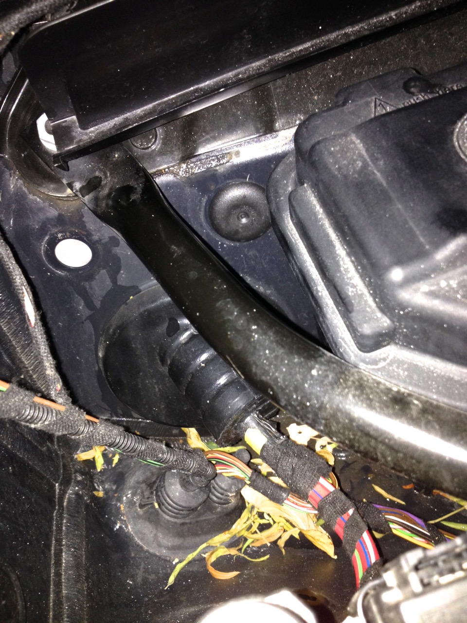
When you puncture the firewall you'll get something inside over here:

My cable after routing it:

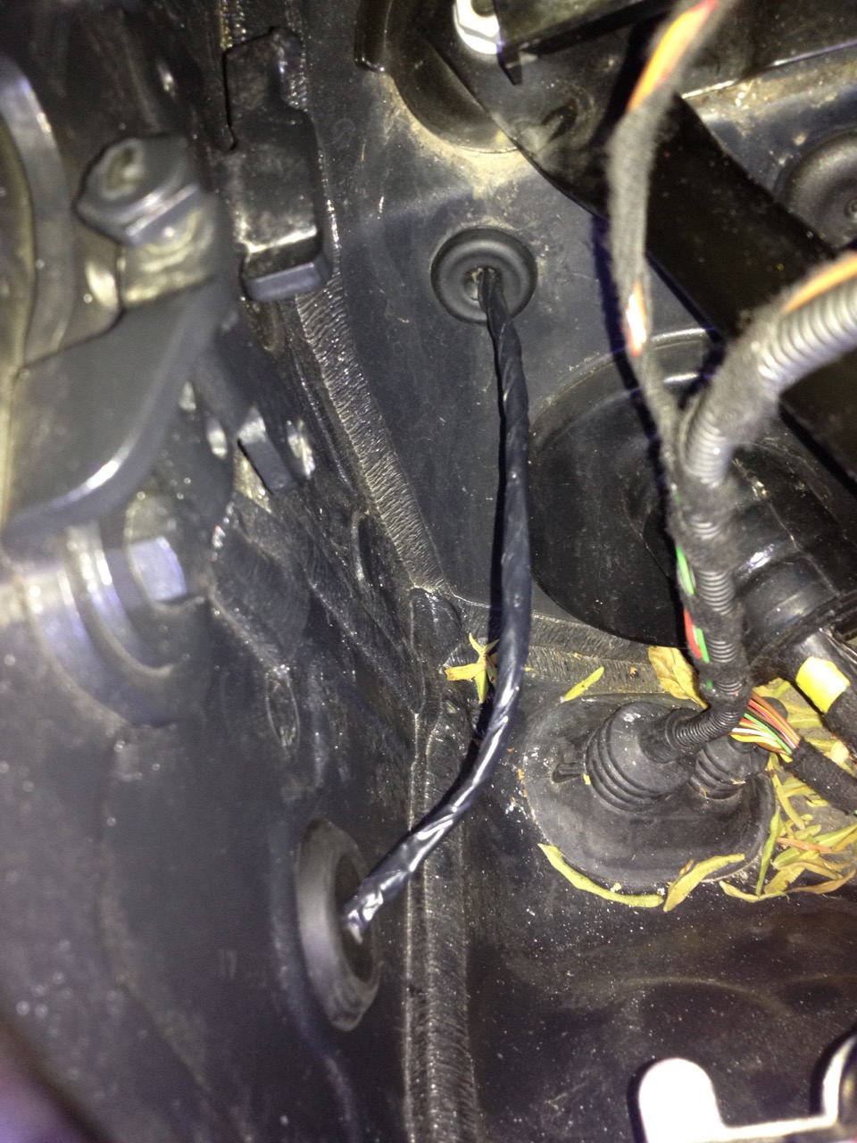
Now that the cable is inside the car, route it to the back of the car.
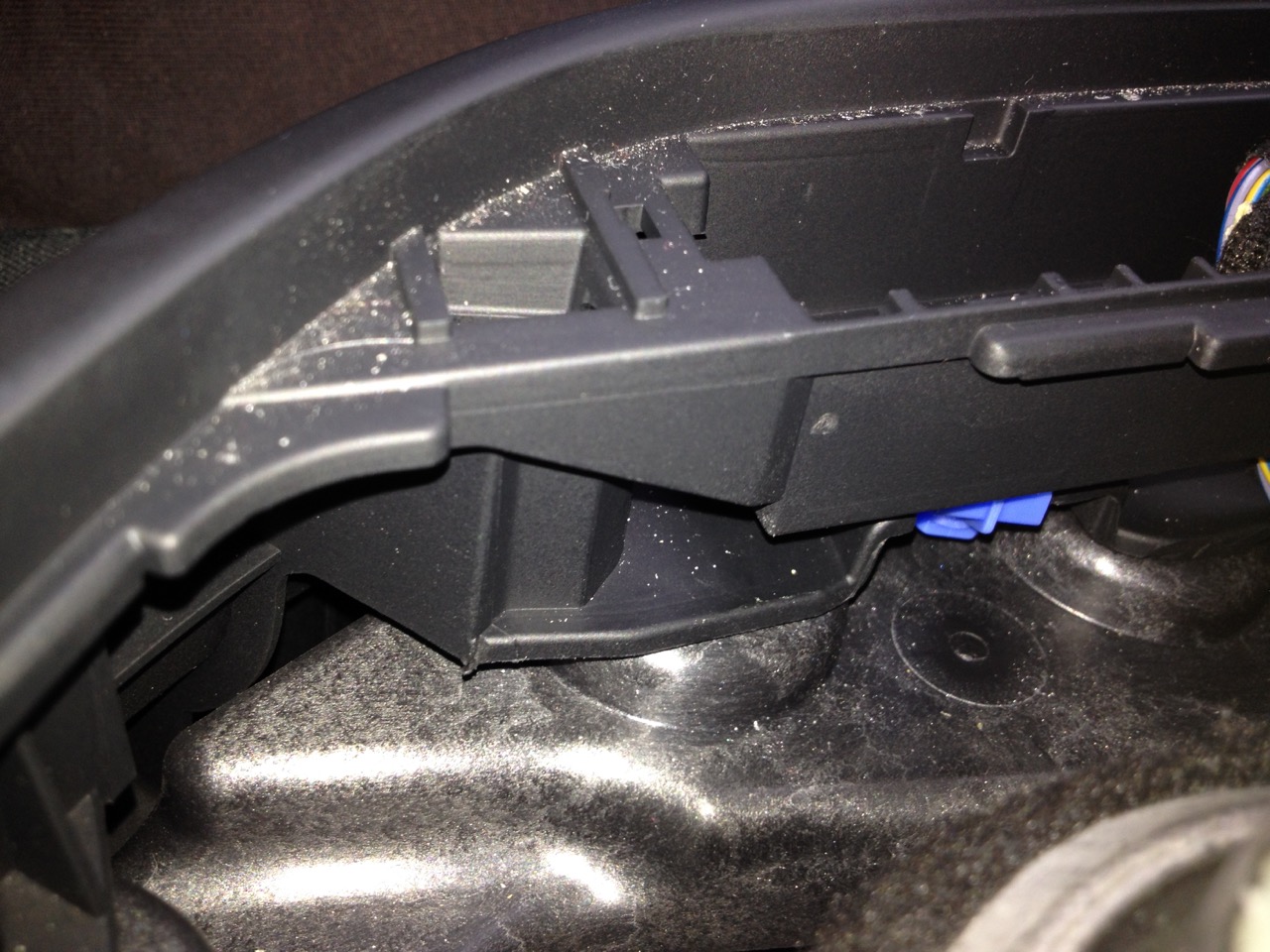
REM
Unplug the REM plug, get the 2 connector modules by unclipping them but be very careful, too much and it will break the sides:
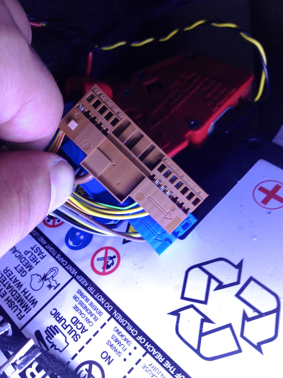
Plug the connector modules inside the plug and reconnect it to the REM again
With all plugged in, reconnect the battery.
Coding
Coding is "easy" and since it's a change in VO you won't need a token for E-SYS
My car already had Rear PDC (option 507) and I want complete PDC (option 508) so we have to change that. Look for "E-Sys - How to change FA in F-series car.pdf" on how to do that.
Afterwards the modules need to be coded.
The simplest way is "ESYS -> Expert -> Code"
Select all ECUs and on "KIS/SVT Target" press "Detect CAF for SWE"
E-SYS will calculate the changes needed for the new VO options
Afterwards press "Code" and wait around 2 minutes
Check that you have PDC working!
Hope this DIY helps someone!