

|
|
|
|
 |

|
 |
BMW Garage | BMW Meets | Register | Today's Posts | Search |
 |

|
BMW 3-Series (E90 E92) Forum
>
Tuner Shootout (Procede / JB) - The Bench Tests
|
 |
| 12-30-2008, 12:30 PM | #1 |
|
Major General
 153
Rep 5,780
Posts |
Obviously this will cause some controversy as many cannot leave that out of topics. But here it is.
This is the first step, next will be road tests with portable data acquisition to log various parameters for a comparison to see if any differences in "feel" can be quantified. At this point I am only testing the PROcede Rev I with the 12-15 Map loaded and JB3 1.2F. Below is mainly the cold hard data. There will be some statements as I feel the data gathering warrants it but it will be based on a professional opinion. If your opinion differs, please respond but do so in a logical manner. As we all know very well, there is a vast difference in the hardware design. The PROcede is a manufactured board using the normal filtering functions and surface mount technology. The JB3 is through-hole design with a minimalist approach as the amount of components on the board could be counted with just the fingers on your hands. Both companies claim their product design is superior and make valid arguments as such. In fact, the simplicity of the JB3 is very interesting that they were able to accomplish what they did and I can absolutely take my hat off to this. However, the lack of filtering and suppression components worries me. In system design you normally do not add additional items for the 99% of the time. It is that unusual 1% that normally requires the extra. But it may end up being a moot issue as time will tell. As a side note, BMS has also done a complimentary job of servicing their customers with trade in. It is almost like purchasing a support contract, or at least that is my interpretation. It is somewhat unprecedented in this market and is truly impressive. On the bench we simulated all signals each unit receives and used the same values for each unit. Meaning, the same boost levels, RPM, etc. were used. To do this mapping we had to determine the actual function of each pin. For the PROcede I already had this and referred to my Cheat Sheet so this was easy and publically available. On the JB3, we had to dig some and actually made a full schematic on it which I will not post unless Terry gives the OK. PROcede Signals B1S1 O2 Sensor Biasing - Analog Output B2S1 O2 Sensor Biasing - Analog Output Speed Sensor - Digital Input and Digital Output Throttle Pedal - Analog Input, Just Tapped, no Analog Output used Crank Position Sensor - Digital Input and Digital Output TMAP - Analog Input and Analog Output Intake Air Temperature Analog Input, Just Tapped, no Analog Output used Boost Control Solenoids - Digital Input and Individual Digital Outputs Fuel Pressure - Analog Input and Analog Output JB3 Signals B1S1 O2 Sensor Biasing - PWM Output B2S1 O2 Sensor Biasing - PWM Output Throttle Pedal - Analog Input, Just Tapped, no Analog Output used Crank Position Sensor - Digital Input, jumpered at terminals TMAP - Analog Input and PWM Output Intake Air Temperature Analog Input, Just Tapped, no Analog Output used Boost Control Solenoids - Single Digital Output Fuel Pressure - Analog Input and PWM Output As you can see, both reference most of the same signals excluding the Speed Sensor which the JB3 does not touch. Is this an advantage to the PROcede, for me, no. I would never push it past 155 but others may want to. The first fundamental difference between the two units is the method in which analog signals are controlled. Both use a traditional analog input A/D. For those who are not familiar, A/D is Analog to Digital conversion. Basically it takes an analog signal, mostly 0 5 VDC in this case and converts it to an integer value represented in A/D counts. For instance as with the JB3, it uses a 10 bit A/D. 10 Bit is 1024 steps. If the voltage measurement range is 0 10 VDC as with many devices, the A/D function chops the voltage up into these steps and returning a value between 0 and 1023 with 0 being 0 VDC and 1023 being 10 VDC. This integer can then be converted to engineering units using the math we learn early on; the linear equation (Y = MX + B). As mentioned, both perform this in the same manner. The difference comes in the way each retransmits the signal. For the PROcede it uses a D/A converter which is basically opposite of the A/D; give it an integer and it outputs the corresponding voltage. This is the same way the other piggybacks perform this operation. In fact, it is the way practically all control systems handle analog control. For instance, the control system I professionally work on, such as 10,000 gallon chemical reactors, use D/A when analog outputs are needed. The JB3 takes a different approach by using a PWM signal. What is a PWM? Pulse Width Modulated; in other words, is a series of pulses measured as a duty cycle signal. A PWM or Duty Cycle signal is typically measured in 0 100%. That is percent is the amount of time the signal is high; basically on. When using a RMS measurement on a PWM signal it appears as a solid analog signal. For instance, give it a 50% duty cycle and you will measure about 2.7 VDC when using a standard volt meter. BMS must have figured out that the DME does some filtering, most likely RMS, of the signals and could use a PWM output. My only exception to this, as it works fine in this case, is lack of filtering. A PWM signal can contain noise and sometimes harmonics at certain frequency/duty cycle ranges. A single resistor and capacitor would have been preferred as currently the PWM signal is attached right to the terminals. But it may very well not be needed and so far appears as such. As an example, in the below images you can see the actual signal difference. Both seem to work just as effectively, just go about it differently. PROcede Analog Input and Output 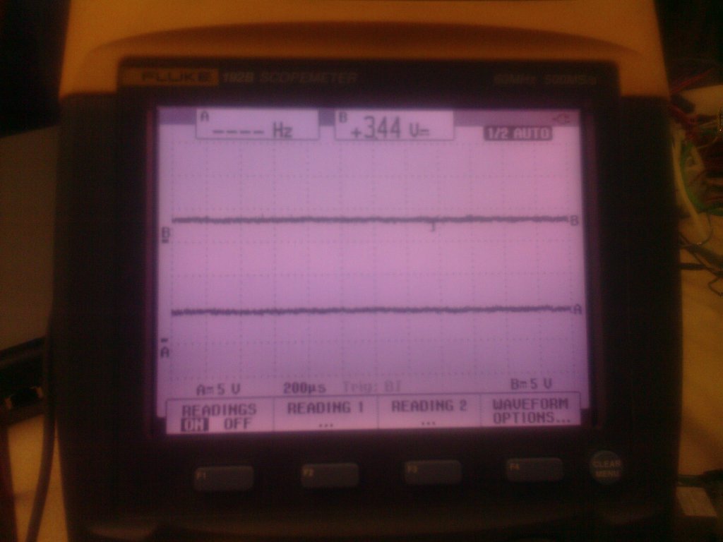 JB3 Analog Input and PWM Output 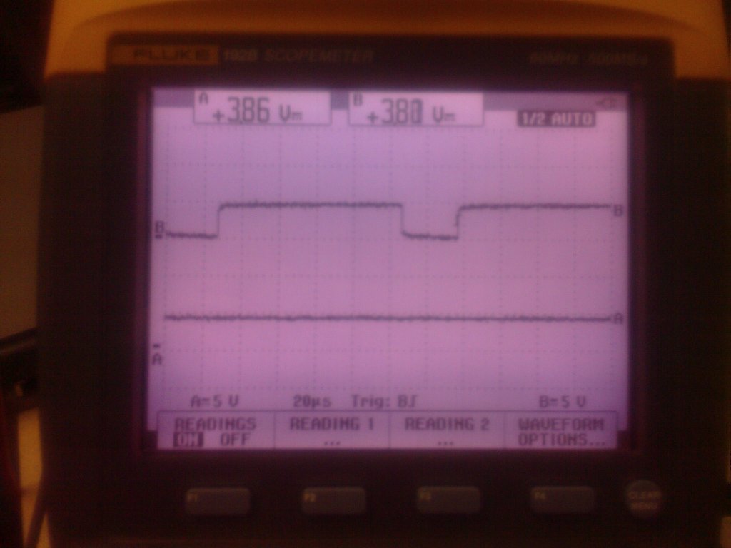 The next difference in the way objectives are handled is in the Boost Control Solenoid. The PROcede has isolated Inputs and Outputs for this. In other words, the PROcede has direct control of the solenoids and if its output failed, you would have no boost at all. The benefit to this is that they can do whatever they want with boost. The drawback is that they are at the mercy of the hardware working and would need to put more scrutiny on the control software; it would be easier to get out of control. But if done correctly, there is more capability to be had. The JB3 sinks the signal through a transistor. Meaning that the DME is still directly connected to the solenoids but the JB3 has the option of adding duty cycle. The benefit to this is that in the event of a JB3 component failure, the DME can still run stock boost levels. The negative is that it limits overall control of the solenoids which is debatable as to if it is needed. The last major area of difference, or at least it appears to be, is in the timing control. The PROcede, once again, uses isolated inputs and outputs. It reads the crank position sensor signal and retransmits a slightly modified signal. The DME uses the CPS to know where the engine is at in its rotation. If you offset the phase (the delay the timing some), you are effectively offsetting the ignition timing. The difficulty in this is that you cannot have abrupt changes in this signal as the DME will detect it as an implausible signal and set a code and/or misfires can occur. As for the JB3, it does not appear the JBS offsets the crank position sensor. We ran numerous tests and could never induce this timing offset. It was previously mentioned that the In and Out pins are jumpered together so it makes since why the since look the same. I then thought maybe some IAT control was done, making the DME think it is warmer than it really is, but this is also just tapped and looks normal. I am not going to say the JB3 is not controlling timing. But it does not appear to be easily measureable and if not, how are you sure it really is? There is no question on how the PROcede is doing what it is doing so I didnt feel there was any harm in illustrating it as most of the intelligence is in the software. I assume the JB3s intelligence is in the software as well. If so, why not discuss the mechanics of how it is doing this function just to clear the air? Obviously this will be up to Terry to decide on but I welcome it. For the testing, I had two CPS simulated signals which were identical but optically isolated so that any control influence on one would not affect the other. I used the PROcede Reader software to set up the simulation with the following data: 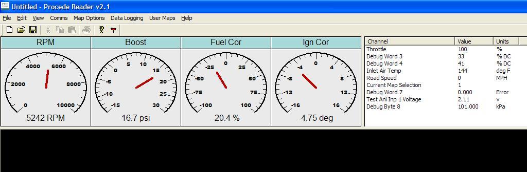 I ran high boost and hot IAT reading to truly push the timing back. As you can see in the screen shot the PROcede was pulling back timing by an indicated -4.75 degrees. When we calculated the timing offset we saw on the scope we came up with -4.8 degrees as shown below. The top signal is the isolated source; the bottom trace is the PROcede output. If you look at the leading rising edges and compare them in the horizontal (time) you can see the PROcede delaying the signal. 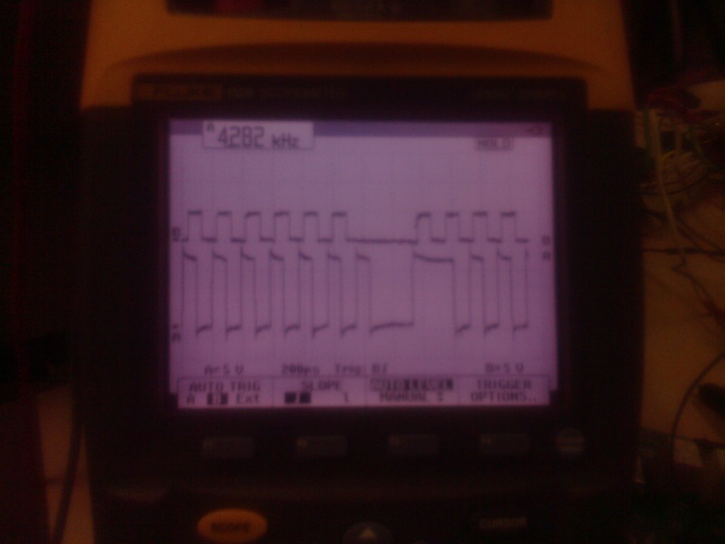 The below is the same sets of signals with no changes to them fed into the JB3. As you can see, there is no timing offset of the CPS signal. 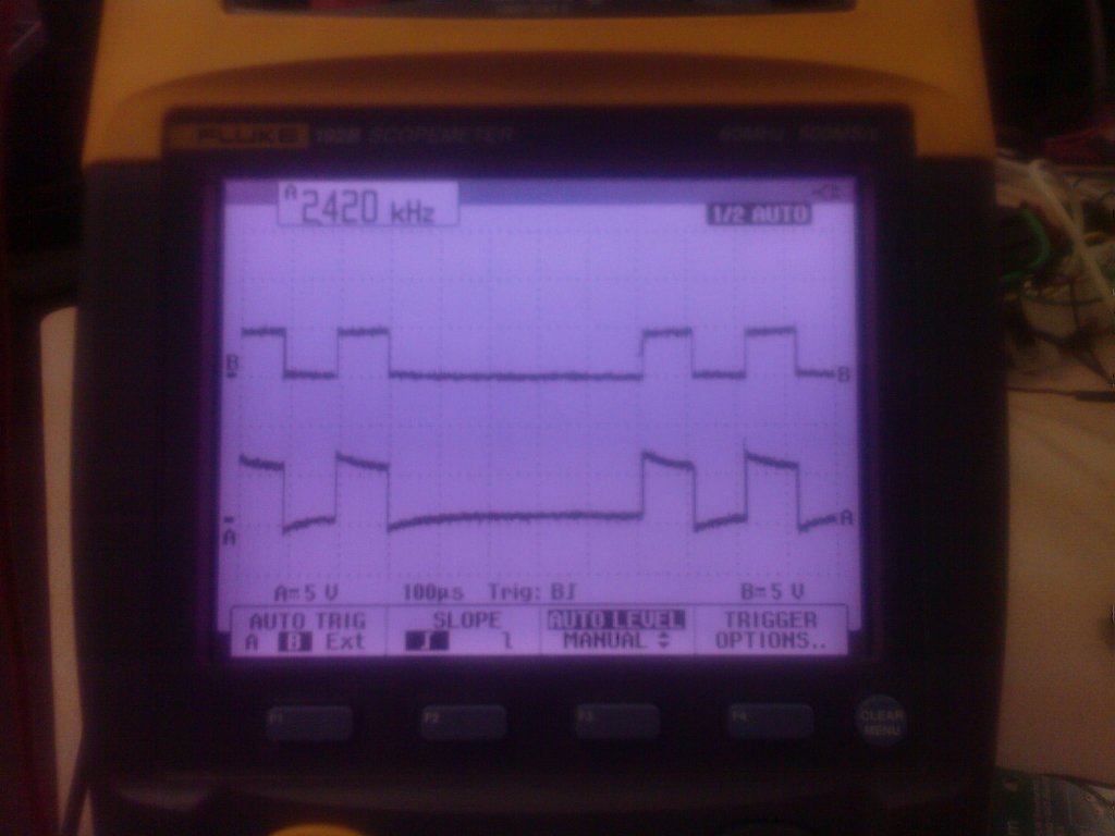 This does not mean the JB3 is not controlling ignition time in some other manner. But it does show there is no CPS timing offset occurring. I am open to suggestions on how it is controlling timing. But at this point it is all on faith. The next installment will be doing some in car data acquisition. Ill put together the test application tonight and wire up a patch harness. I will log IAT, RPM, Throttle Pedal Position, Throttle Plate Position, Fuel Pressure and Boost. Any other suggestions? Ill capture some Tab Delimited files and post them for everyones analysis as well as offer mine. What we will be looking at is stability and response. That is it for now, let the whining begin.  |
|
|
| 12-30-2008, 12:44 PM | #3 |
|
Major General
148
Rep 5,389
Posts |
No whining...just a pat on the back for your time, effort, and technical knowledge to do these comparison tests. Although I am not an electrical engineer and have no idea what you're talking about (most of what you're testing anyway
), I do appreciate what you're doing. So, keep up the great work, Scalbert! 
__________________
 |2009 RENNtech MB C63 AMG | Black/Black Leather/Black Maple | Premium II | MultiMedia | iPod | | TeleAid | Charcoal Filter Delete | BMC High-Flow Air Filters | High-Flow Secondary Cats | Clear Side Markers | |
|
Appreciate
0
|
| 12-30-2008, 12:51 PM | #6 |
|
Lieutenant Colonel
 63
Rep 1,914
Posts |
 from me too even though i've no idea what you were talking about..lol. ive JB3 but i can appreciate tests/facts as well as learning the pros and cons of each tune. from me too even though i've no idea what you were talking about..lol. ive JB3 but i can appreciate tests/facts as well as learning the pros and cons of each tune. |
|
Appreciate
0
|
| 12-30-2008, 12:57 PM | #8 |
|
Night Sh1ft

458
Rep 3,079
Posts
Drives: F95 X5MC LCI
Join Date: Oct 2007
Location: It's bobsled time
|
nice man
good to see it all coming together look forward to your further testing
__________________
"Your first 10,000 photographs are your worst. ― Henri Cartier-Bresson |
|
Appreciate
0
|
| 12-30-2008, 01:02 PM | #11 |
|
Private
 1
Rep 51
Posts |
I noticed you said you were using the older Procede Rev1 and the newer JB3 1.2. Just wondering if not using both of the newest products (or both of the older) would make a difference in what you're testing? In other words is there any big differences with the Rev1 and Rev2 that would change anything you have done or will be doing?
Great work so far! Very interesting. |
|
Appreciate
0
|
| 12-30-2008, 01:04 PM | #12 | |
|
Major General
153
Rep 5,780
Posts |
Quote:
As for JB3 1.2, Terry indicated he would send me a new chip. |
|
|
Appreciate
0
|
| 12-30-2008, 01:05 PM | #13 | |
|
Lieutenant
 
44
Rep 428
Posts |
Rev I. and Rev II. both use the same firmware and maps. Regardless of the hardware version, the results of this test would remain the same.
Edit: Scalbert beat me to the punch. Quote:
|
|
|
Appreciate
0
|
| 12-30-2008, 01:06 PM | #14 | |
|
1737
Rep 17,960
Posts
Drives: A Lot
Join Date: Sep 2006
Location: SF Bay, CA
iTrader: (0)
Garage List 2018 Ducati Panigal ... [0.00]
2016 Mazda CX5 [0.00] 2017 Aprilia Tuono ... [0.00] 2019 BMW M2 Competi ... [0.00] 2015 BMW M5 Competi ... [10.00] 2016 Ducati XDiavel S [0.00] 2016 AMG GT S [0.00] 2011 Ferrari 458 It ... [0.00] 2017 Charger Hellcat [0.00] 2015 KTM Super Duke ... [0.00] 2016 KTM RC390 [0.00] |
Quote:
Shiv |
|
|
Appreciate
0
|
| 12-30-2008, 01:08 PM | #15 | |
|
First Lieutenant
17
Rep 310
Posts |
Quote:
|
|
|
Appreciate
0
|
| 12-30-2008, 01:10 PM | #16 |
|
Team Zissou
3065
Rep 10,197
Posts |
Great work scalbert! I think I can speak for everyone and give a big "thank you" for this work you've been doing.
In other news, having only "faith" that a tune is controlling timing isn't good enough in my book. It'll be interesting to see if Terry can explain how he goes about accomplishing it with the Juice Box |
|
Appreciate
0
|
| 12-30-2008, 01:11 PM | #17 | |
|
Major General
153
Rep 5,780
Posts |
Quote:
|
|
|
Appreciate
0
|
| 12-30-2008, 01:14 PM | #18 | |
|
1737
Rep 17,960
Posts
Drives: A Lot
Join Date: Sep 2006
Location: SF Bay, CA
iTrader: (0)
Garage List 2018 Ducati Panigal ... [0.00]
2016 Mazda CX5 [0.00] 2017 Aprilia Tuono ... [0.00] 2019 BMW M2 Competi ... [0.00] 2015 BMW M5 Competi ... [10.00] 2016 Ducati XDiavel S [0.00] 2016 AMG GT S [0.00] 2011 Ferrari 458 It ... [0.00] 2017 Charger Hellcat [0.00] 2015 KTM Super Duke ... [0.00] 2016 KTM RC390 [0.00] |
Quote:
And then ask yourself why do we run more timing retard? Running less or none is just a key stroke away. The only maps that run little or no timing retard are race gas maps. Do you know why? Shiv |
|
|
Appreciate
0
|
| 12-30-2008, 01:16 PM | #19 |
|
Colonel
 52
Rep 2,225
Posts |
Wow. I read it twice and I'm still scratching my head.
I appreciate the effort your making scalbert. I look forward to the next set of testing, even though it's more then a bit over my head.
__________________
07 335i sedan | Steptronic | Black saphire | Terra | ZPP | ZSP | Cold Weather | CA | PDC | Nav | OEM Alarm
|
|
Appreciate
0
|
| 12-30-2008, 01:18 PM | #20 | |
|
274
Rep 6,510
Posts |
This is from the jb3 launch details... its what was provided by Terry when we first started taking orders for the jb3 back in august. It might help people understand what is what, and what i/o is used for which things.
Quote:
|
|
|
Appreciate
0
|
| 12-30-2008, 01:18 PM | #21 | |
|
First Lieutenant
17
Rep 310
Posts |
Quote:
|
|
|
Appreciate
0
|
| 12-30-2008, 01:22 PM | #22 |
|
Second Lieutenant
14
Rep 206
Posts |
This is awesome, although some of this kind of files in that 'uh ok, cool thanks I guess... ' part of my brain it is interesting that the JB3 doesn't have a clear method of timing control. I have a suspicion that is is controlling it somehow but I have no idea how it would be if it does no have the taps directly for the system. It seems to me the only other methods of even affecting timing control would be through modifying sensor signals to the ecu for other parameters such as the IAT as you suggested. However I would think that doing so would have knock on effects on other areas besides ignition timing. Some explanations on how they make this work would be nice

__________________
 |
|
Appreciate
0
|
 |
| Bookmarks |
|
|


 Any man who can drive safely while kissing a pretty girl is simply not giving the kiss the attention it deserves. ~Albert Einstein


